DIY Systainer
- interoperates with Festool Systainer
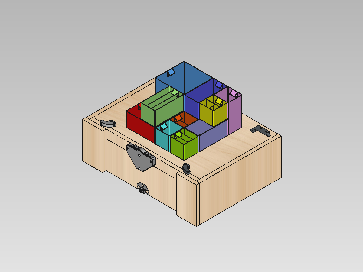
- provides flat internal space without protrusions
- allows for better transport via interlocking
- helps to save money by building it yourself
The STL pack offered here contains 3d-printable components to build your own DIY Systainer.
Why
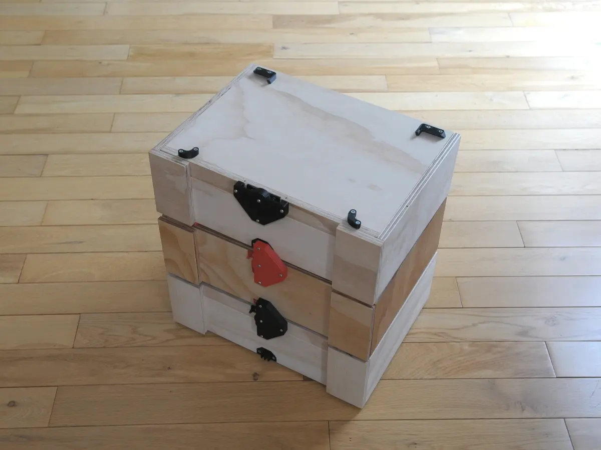
Festool Systainer cases are stackable, interlocking, and just great for storing things. The major downside is their huge price. So, I decided to build my own that is compatible with the Systainer.
Demo
This video demonstrates completed DIY Systainers:
This video shows DIY Systainers used as base for a micro lathe, and the one below it as drawer for collets. In this modification, instead of top-open lid, I used slide-out compartment so that to get access to tools without lifting the box on top. The walls were made taller by 25.4mm (1”) to regain space that was lost to the slides:
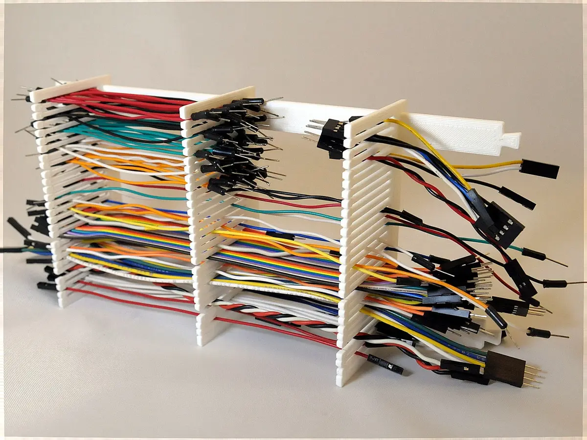
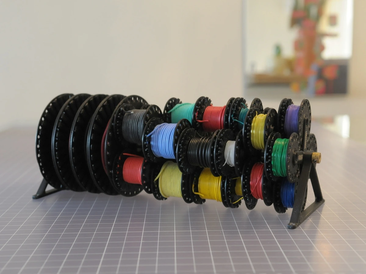
Related Projects
These projects were created to integrate with DIY Systainer having internal height of 101 mm (4”):
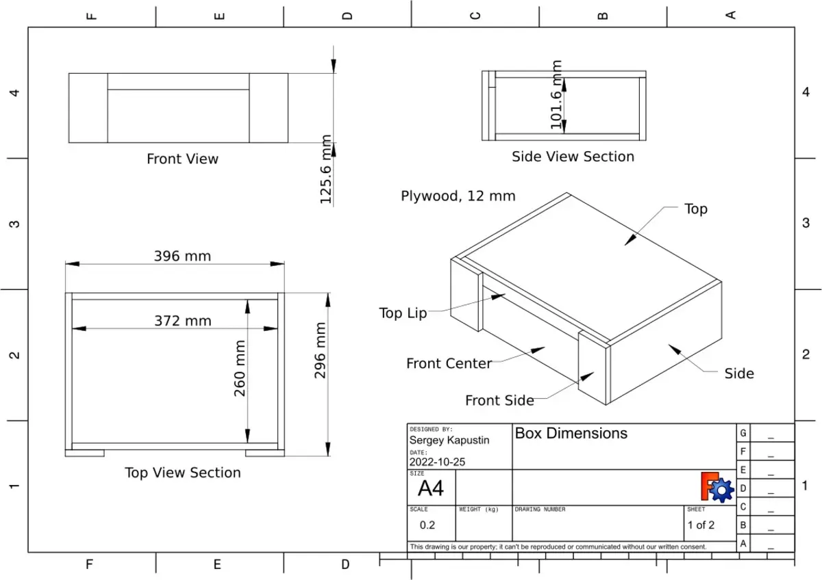
Assembly
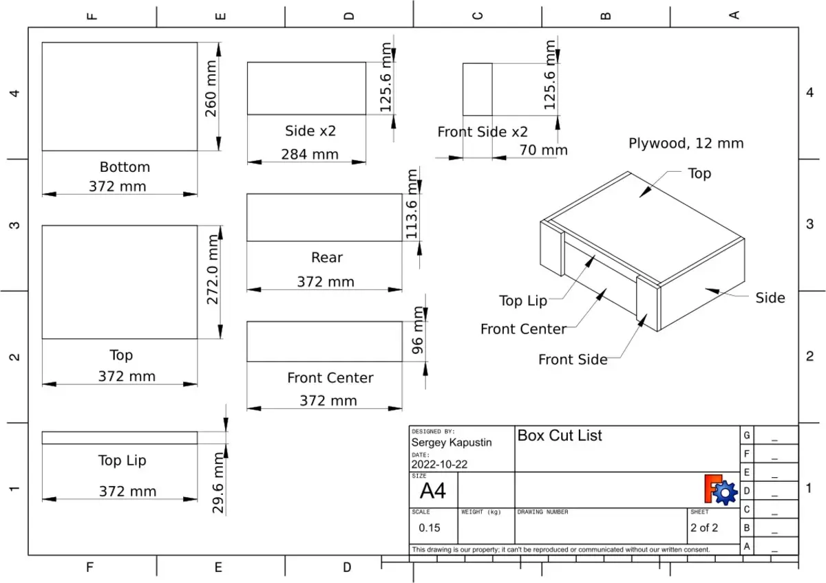
Cut List
The panels can be joined with dowels, plain screws, etc. It’s important to maintain precise cuts and clean/square joints for interconnection mechanism to work properly.
Inlay Parts
There are two jigs for inlay parts: dovetail and latch port. The jigs are meant for use with a router and guide bushing having external diameter of 11 mm (0.438”) and router endmill with 6.35 mm diameter (0.25”).
To place the jigs, first draw a vertical line though the middle of front center and top lip parts. Then align a notch on the jig with the line and fix the jig with two screws for stability during routing operation.
It is easier to hold down the parts for routing before the box is assembled.
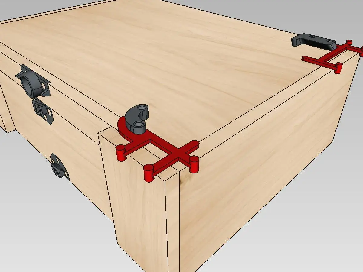
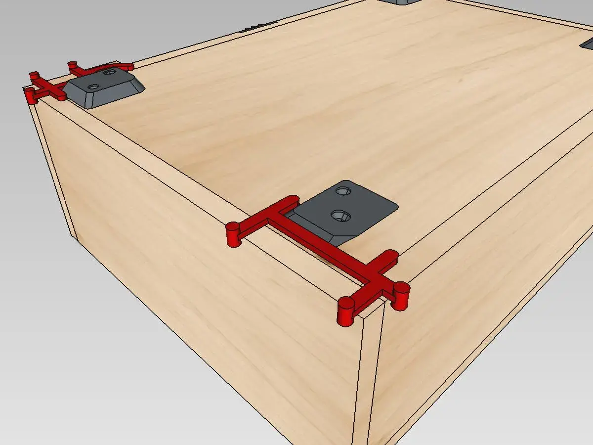
Foot Positioning
Positioning jigs assist in marking the attachment points for feet and feet stoppers. Elephant-looking jig is used to position front feet and stoppers for both left or right side by just flipping it. Straight-line jig is used for rear feet and stoppers, left or right.
Mark attachment points after assembling the box.
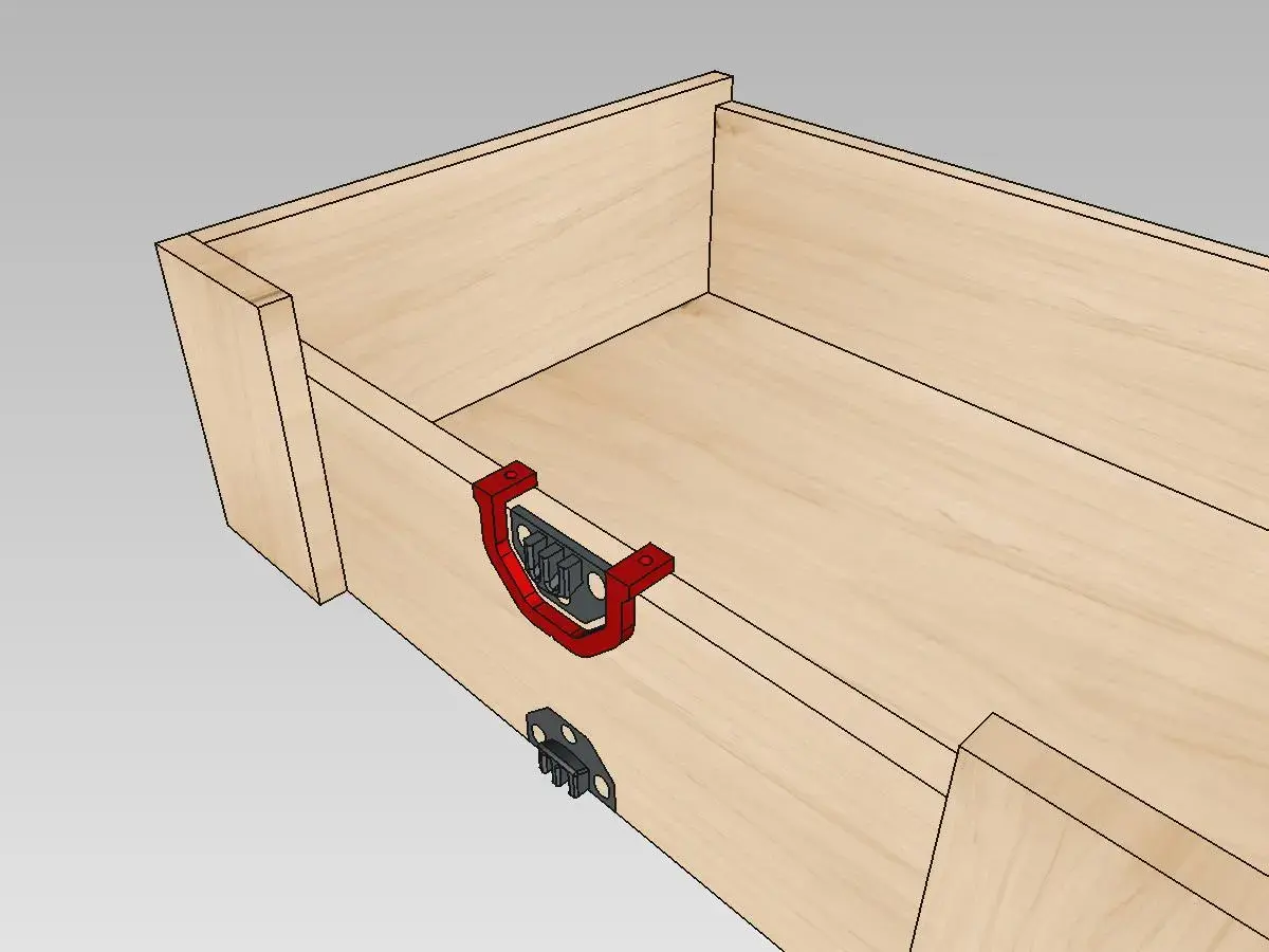
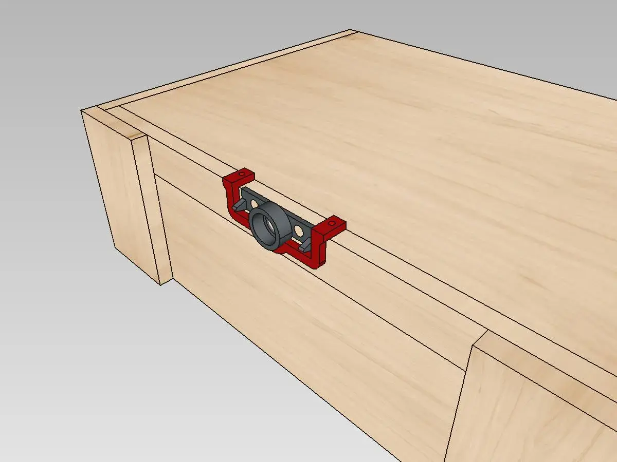
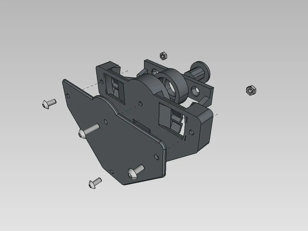
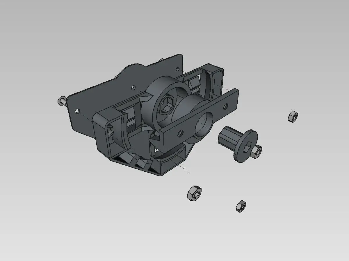
Latch
Required extra hardware:
- Perimeter bolts: M3x6mm x3
- Center bolt: M3x10mm x1
- Nuts: 3mm x4
Lid Hinges
A few mini brass hinges for cabinet/jewelry boxes work ok. This could be a weak link when hooking up heavy boxes and trying to lift the whole stack with a top box.
Order of Assembly
Using dowels and glue, the following order of assembly worked for me:
- Attach rear, front-center panels to the buttom panel
- Attach side panels
- Join the top and the top lip panels
- Attach the top to the rear panel using hinges. The latch will get stuck unless top panel closes flush with the front-center. So, make sure front-center and top lip panels are flush when setting them up
- Attach dovetails
- Assemble the latch including latch port. Turn the port 90 degrees and attach it to the top lip with a flat-head screw; repeat for the other side. Loosen or tighten center bolt for less or more friction
- Use positioning jigs to mark hole locations for feet and feet stoppers. Note that feet have one hole elongated. This could be used during assembly for minor adjustments so as to better align feet and corresponding stoppers. If concerned about fit, I would mark just the elongated hole in the middle, attach a foot with one screw, fit and adjust. When satisfied, attach the second screw.
- Fasten a nylon line to two screws, on box side and on the top, so that to constrain opening the top to just past 90 degrees
- Attach front side panels. The panels are mostly needed to prevent the latch from catching on things when box is being moved around. The panels may interfere with closing of the top if they are affixed at some weird angle
3D Printer Settings
Working prints were produced on Prusa MINI with:
- 0.6 mm nozzle
- 0.3 mm QUALITY
- 15% infill
- 4 perimeters
- PLA
- Support on build plate only